REPARACIÓN NIKON D70s. CAMBIO DEL SENSOR CCD
REPAIR NIKON D70s. CCD SENSOR CHANGE
REPAIR NIKON D70s. CCD SENSOR CHANGE
La cámara se probó con varias ópticas MF y AF, con y sin flash propio y externo y con todos los modos que ofrece. Funcionaba bien pero la única imagen que aparecía en el display era una mancha blanca que cubría casi la mitad superior derecha. Ver imagen a continuación.
The camera was tested with various MF and AF lenses, with and without flash external own all modes offered. It worked well but the only image that appeared on the display was a white patch covering almost half top right. See image below.

The camera was tested with various MF and AF lenses, with and without flash external own all modes offered. It worked well but the only image that appeared on the display was a white patch covering almost half top right. See image below.

Descarté el obturador como fuente de la avería simplemente porque “me sonaba bien”, me sonaba a Nikon.
Procedo al desmontaje empezando por la base.
I discarded the shutter as a source of damage simply because "it sounded good," sounded to Nikon.
I come to dismantling starting at the base.
I discarded the shutter as a source of damage simply because "it sounded good," sounded to Nikon.
I come to dismantling starting at the base.

Siguiendo el procedimiento señalado en la reparación de la Nikon D300 (lector de tarjeta de memoria CF) asignamos una letra a los diferentes tornillos y procedemos a guardarlos por separado para hacer el montaje correcto.
Unos sobrecitos de papel autoconfeccionados y etiquetados nos servirán para este propósito.
Following the procedure outlined in the repair of the Nikon D300 (memory card reader CF) assign a letter to the various screws and proceed to save them separately for correct mounting.
A self-made paper envelopes and labeled will serve for this purpose.
Following the procedure outlined in the repair of the Nikon D300 (memory card reader CF) assign a letter to the various screws and proceed to save them separately for correct mounting.
A self-made paper envelopes and labeled will serve for this purpose.

El siguiente paso consiste en extraer el cable FPC que interconecta la placa compresora de datos con el display y botones traseros.
The next step involves removing the FPC cable interconnecting the compressor data plate with the display and back buttons.
The next step involves removing the FPC cable interconnecting the compressor data plate with the display and back buttons.

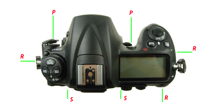
A continuación vamos a desatornillar la parte posterior del cuerpo retirando los cuatro tornillos que la sujetan, dos a cada lado de la cámara.
Then we will unscrew the back of the body by removing the four screws holding it, two on each side of the camera.
Then we will unscrew the back of the body by removing the four screws holding it, two on each side of the camera.

Los tornillos, llamados D en la foto, se encuentran en el lugar señalado por las líneas rojas.
Retirar y guardar el escudo de metal del conector USB que actúa como una pinza con las dos placas (compresora de datos y placa base)
Una vez retirada la parte trasera tenemos que cortocircuitar el condensador que hay a la derecha, junto al compartimento de la batería, es el condensador del flash y tiene, generalmente, una carga elevada.
Si lo hacemos con una resistencia de 2.000 ohmios evitaremos un desagradable chispazo.
The screws on the photo called D are in the place indicated by the red lines.
Remove and store the metal shield of the USB connector serving as a clamp with two plates (data compression and motherboard)
After removing the back we have to short the capacitor to the right, next to the battery compartment, is the flash capacitor and generally has a high load.
If we do so with a resistance of 2000 ohms avoid a nasty spark.

Ahora pasamos a la placa de gestión de datos. La que está en la parte de abajo y retiramos las FPC’s que están marcadas en rojo. La C2 requiere mucho cuidado para no romper la pieza negra de bloqueo de la cinta. La C3 tiene una pieza de ferrita que actúa como anillo de bloqueo de señales de Alta Frecuencia que provienen de la placa de gestión de la alimentación externa. Retirarla y guardarla.
Now we turn to the data controller board. The one on the bottom and removed the FPC's that are marked in red. The C2 requires careful not to break the lock black piece of tape. The C3 has a piece of ferrite ring acts as blocking high frequency signals coming from the management board external power. Remove it and save it.
Now we turn to the data controller board. The one on the bottom and removed the FPC's that are marked in red. The C2 requires careful not to break the lock black piece of tape. The C3 has a piece of ferrite ring acts as blocking high frequency signals coming from the management board external power. Remove it and save it.

Quitamos y guardamos los cuatro tornillos F. Con esto, la placa se puede retirar. PRIMERO LEER EL SIGUIENTE PÁRRAFO.
Las dos caras de la placa donde apreciamos el conector (marcado X) sin cables que se enchufa en la otra placa y que extraeremos con cuidado.
We remove and save the four screws F. With this, the plate can be removed. FIRST READ THE FOLLOWING PARAGRAPH.
The two faces of the plate where we see the connector (marked X) wirelessly that plugs into the other plate and will extract carefully.
We remove and save the four screws F. With this, the plate can be removed. FIRST READ THE FOLLOWING PARAGRAPH.
The two faces of the plate where we see the connector (marked X) wirelessly that plugs into the other plate and will extract carefully.


Cuidar de que no se pierdan las dos bloques de malla elásticos con revestimiento metálico que hay alrededor del conector USB, se despegan con facilidad.
Tras retirar esta placa veremos esta otra, la cual no tenemos necesidad de retirar pero trabajaremos sobre ella.
Ensure that not lost two elastic mesh blocks with metal coating around the USB connector there, come off easily.
After removing this plate see this one, which we have no need to remove but we will work on it.

Debajo de la cinta FPC C5 (el que viene de la placa del sensor CCD) encontraremos un conector blanco que retiramos de su ubicación. Ver en la imagen el C6.
Under FPC ribbon C5 (which comes from the CCD sensor board) we find a white connector withdraw from your location. View image in the C6.
Under FPC ribbon C5 (which comes from the CCD sensor board) we find a white connector withdraw from your location. View image in the C6.

Retirando los siguientes cuatro tornillos G ya podemos sacar de su ubicación la placa con el sensor CCD. En esta imagen ya están retirados.
Removing the following four screws G and can draw from its location the plate with the CCD sensor. In this image are now retired.
Removing the following four screws G and can draw from its location the plate with the CCD sensor. In this image are now retired.

La anilla plana de ferrita está sujeta con un trozo de cinta adhesiva.
¡¡¡VOILÁ, AQUÍ ESTÁ EL SENSOR!!!
The flat ferrite ring is secured with a piece of tape.
¡¡¡VOILÀ, HERE IS THE SENSOR!!!
The flat ferrite ring is secured with a piece of tape.
¡¡¡VOILÀ, HERE IS THE SENSOR!!!

El sensor se vende como un conjunto: Base metálica, placa de interface de datos y alimentación junto con la pastilla del CCD.
En la siguiente imagen vemos el área que debemos limpiar muy bien soplando con la pera antes de poner el nuevo sensor.
The sensor is sold as a set: CCD chip, plate power and data interface over a metal plate.
In the next picture we see the area thoroughly clean with pear blowing before putting the new sensor.
The sensor is sold as a set: CCD chip, plate power and data interface over a metal plate.
In the next picture we see the area thoroughly clean with pear blowing before putting the new sensor.

Los puntos de referencia sirven para ubicar correctamente el nuevo sensor.
Cuando colocamos el nuevo sensor, presionamos con los dedos desde el ángulo superior izquierdo (según la imagen) para que los topes que tiene el nuevo módulo coincidan con precisión y no se muevan mientras ponemos los tornillos. (Apunte: poner los cuatro tornillos sin apretarlos y luego realizar la operación de ajuste con la mano izquierda mientras colocamos los tornillos con la derecha).
The reference points are used to properly position the new sensor.
When we put the new sensor, finger pressed from the upper left (as shown) for the stops that have the new module accurately match and do not move while putting the screws. (Aim: to put the four screws loosely and then perform the setting operation with the left hand while put the screws to the right).
AÑADIDO el día 7/06/2013.
ADDED on 06/07/2013.
Después de poner el sensor en su ubicación viene la parte más delicada y sensible de todo el proceso de reparación: ajustar el sensor por medio de los cuatro tornillos que lo sujetan para que quede perfectamente perpendicular al plano de imagen.
Es esta una labor de prueba-error, salvo que dispongamos de los medios que tienen los talleres SAT de Nikon.
No se trata de poner esos tornillos en su sitio y apretarlos para que el sensor quede bien sujeto en su ubicación definitiva.
La junta que debemos limpiar, según se especifíca antes de la última imagen, es de material elástico y permite un margen de presión para poder realizar ese ajuste.
Quién decida emprender la tarea de cambiar el sensor CCD debe conocer la dificultad que supone ese ajuste.
This is a work of trial and error, unless we have the means to have Nikon SAT workshops.
It is not put those screws in place and tighten so that the sensor is properly secured in its final location.
The board that we clean, as specifies before the last image is of elastic and allows pressure range to perform this adjustment.
Who decides to undertake the task of changing the CCD must know the difficulty of that adjustment.
TRIMMER TOOL TO DOWNLOAD THE ENERGY FROM THE FLASH.
Este es el artilugio usado para descargar el condensador del flash.
Para confeccionarlo se necesitan: una resistencia de 2.200 ohmios y 2 watios, 15 o 20 centímetros de cable fino aislado, soldador y estaño y cinta aislante.
Se corta el cable por la mitad y se pelan las puntas (unos tres milímetros es suficiente).
Se sueldan estos cables a la resistencia como se ve en el dibujo.
Se cubre con cinta aislante el conjunto de resistencia y soldaduras para que todo esté protegido del contacto con nuestros dedos.
Los extremos de los cables que quedan libres se estañan para que no se abran las puntas.
Para descargar el condensador se "puentea" el mismo con ese artilugio juntando la punta "A" con el terminal "a" y el "B" con el "b".
This gadget is used to download the energy from the flash capacitor.
To tailor it needed: a resistance of 2,200 ohms and 2 watts, 15 or 20 inches in isolated thin wire, tin solder and tape.
Cable is cut in half and peel the tips (about three millimeters is sufficient).
These leads are soldered to the resistance as seen in the drawing.
It is covered with electrical tape the resistor assembly and welding so that everything is protected from contact with our fingers.
The cable ends are left free so that no tinned split ends.
To download the capacitor "bypasses" the same with that contraption joining the tip "A" terminal "a" and "B" with "b".