The English translation was carried out with Goolge Translator.
ATENCION. Antes de considerar este tutorial como una herramienta de trabajo debo advertir que NO me responsabilizo de cualquier avería, rotura o fallo que se produzca en cualquier cámara que no haya sido manipulada, exclusivamente, por mi.
ATTENTION. Before considering this tutorial as a working tool I must warn you NOT take responsibility for any damage, breakage or failure occurring in any camera that has not been handled exclusively by me.
La avería apareció por el uso de una tarjeta Compact Flash sin marca que me estropeó el módulo CF de mi cámara Nikon D300. En las dos imágenes siguientes el nuevo módulo CF.
The fault appeared on the use of a Compact Flash card unbranded. In the two pictures below the new module CF.
El mensaje que aparecía en el display superior, "CHA" me indicaba que la cámara no podía acceder a la tarjeta CF. Cambié de tarjeta y probé con otras dos que son de una marca de prestigio y seguía dando el mismo mensaje. El problema no estaba en la tarjeta (ahora ya no).
The message that appeared on the upper display, "CHA" told me that the camera could not access the CF card. I changed my card and tried with other two being a prestige brand and kept giving the same message. The problem was not in the card (not anymore).
Hice un reset de todo lo que se puede resetear y probé con diferentes objetivos pero no sirvió de nada (mejor dicho, sirvió para descartar todos esos elementos como causa de la avería) de manera que me decidí por la intervención sobre el dispositivo para solucionar el problema.
I did a reset of everything that can be reset and tested with different lenses but it did not help (or rather, served to discard all those elements as the cause of the fault) so I settled for the intervention on the device to solve the problem.
Busqué información en la WEB y no encontré nada (posiblemente no supe buscar bien) asi que me propuse encontrar la solución por mi mismo.
I looked for information on the Web and found nothing (possibly not know look good) so I set out to find the solution by myself.
Compré por ebay el módulo CF y la placa base (Motherboard o Mainboard que dicen los angloparlantes) porque en una inspección ocular descubrí que faltaban pines en el conector del módulo CF y, si esos pines no estaban en su sitio, podían estar haciendo mucho daño en otra parte de la circuitería.
I bought on ebay the CF module and motherboard (Motherboard or Mainboard English speakers say) because an inspection found missing pins in the CF module connector and if those pins were not in place, they could be doing a lot of damage in another part of the circuitry.
Estos son las herramientas que yo he usado para desmontar la cámara y cambiar el módulo CF. Todos los tornillos son del tipo estrella (también llamados Phillips).
These are the tools I used to disassemble the camera and change the module CF. All screws are Phillips type.
Es importantísimo que los tornillos no se mezclen. Hay que preparar un recipiente con ONCE compartimentos etiquetados o ONCE recipientes con su etiqueta (del 1 al 11, de la A a la K, o como mas nos guste). Fijándose en los compartimentos de la caja de plástico transparente se pueden ver unas pequeñas etiquetas que van de la A a la K, ese es mi sistema para no mezclar los tornillos.
It is important that the screws do not mix. We must prepare a container with compartments labeled or labeled envelopes (from 1 to 11, A to K, etc.) Looking at the compartments of the plastic box you can see some small labels ranging from A to K, that is my system not to mix the screws.
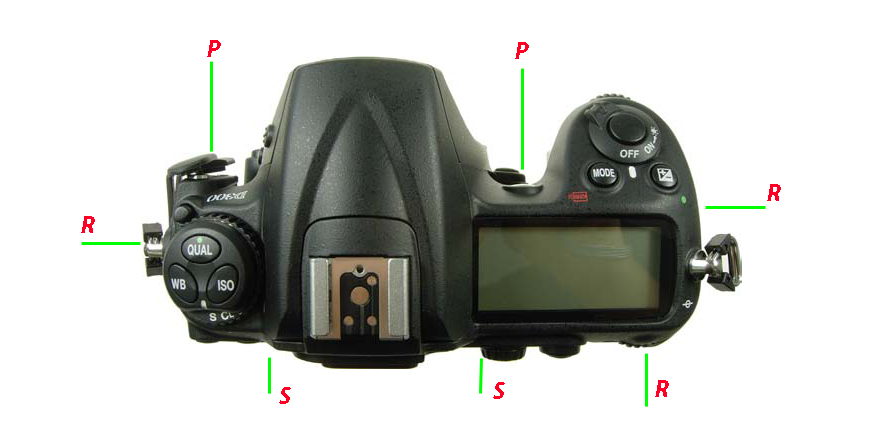
Para probar si el destornillador elegido nos sirve tenemos cinco tornillos externos visibles y accesibles en elexterior del cuerpo. Hay dos, uno arriba y otro abajo de la puerta/goma de los conectores HDMI-USB-DC IN-VIDEO out. Estos tornillos se retirarán en el momento adecuado, ahora NO. Hay un tercero visible junto a la tapa de la batería. Podemos probar en uno de ellos si el tamaño de la punta del destornillador elegido es el correcto.
To test whether the chosen screwdriver serves us we have five external screws visible and accessible on the outside of the body. There are two, one up and one down the door / rubber connectors DC HDMI-USB-IN-VIDEO out. These screws will be removed at the right time, now NO. A third is visible next to the battery cover. We can try one of them if the size of the tip of the screwdriver chosen is correct.
MANOS A LA OBRA
GET TO WORK
El primer paso consiste en retirar un tornillo que se encuentra en el fondo del compartimento de la batería. Guardar como tornillo nº1 o letra A. (A partir de ahora omitiré el nº).
Este tornillo tiene como única misión asegurar la cubierta de goma a la altura de la marca roja (esa goma que cubre lo que llamaremos el grip fijo del cuerpo, la parte por donde sujetamos la cámara con los dedos de la mano derecha). Esa goma tiene una pequeña protuberancia con un agujero que se introduce por el interior del cuerpo y por el agujero pasa el citado primer tornillo.
The first step is to remove a screw located at the bottom of the battery compartment. Save as screw # 1 or letter A. (From now I omit the number).
This screw has the sole mission to ensure the rubber cover at the height of the red (rubber covering that what we call the fixed grip body, the part where we subject the camera with the fingers of the right hand). This rubber has a small bump with a hole which is inserted inside the body and passes through the hole in said first screw.
Parece ser que lo correcto es retirar esa goma por completo para acceder a cuatro tornillos que se esconden debajo de ella. Yo no lo hice. La única goma que es necesario despegar por completo del cuerpo es la que está en la base de la cámara.
It seems that the right thing is to remove the rubber completely to access four screws hidden underneath. I did not do. The only rubber is necessary to completely detach from the body is that which is at the base of the body.
El segundo paso es retirar la puerta del compartimento de la batería y se hace poniendo esta tapa en ángulo de 45º con respecto a la base y tirando de ella en esa dirección (45º) y veremos que se desprende sin problemas (se puede invertir el orden del primer y segundo paso). Ver la flecha roja en imagen de abajo.
The second step is to remove the door to the battery compartment and makes putting this cover at an angle of 45 ° with respect to the base and pulling it in that direction (45 °) and we see that it appears smooth (you can reverse the order the first and second step). See the red arrow in the image below.
Ahora despegamos, con cuidado de no romperla, la goma de la base. Una vez retirada y respetando al máximo la superficie con pegamento, (luego nos hará falta para volver a ponerla en su sitio) se procede a retirar los tornillos en este orden:
Los tres marcados con una flecha verde (guardar como B)
Los cinco marcados con flecha color azul claro (guardar como C)
ATENCIÓN la tapa de la base aún no está suelta.
Now take off, being careful not to break it, the rubber base. After removing and respecting the maximum glue surface, (then we will need to put it back in place) proceed to remove the screws in this order:
The three marked with a green arrow (save as B)
The five marked with light blue arrow (save as C)
ATTENTION base cover is not yet released.

Despegar la goma del grip, por la parte de abajo, para acceder a dos tornillos (tornillos D) que se encuentran debajo de la misma (y que en la fotografía ya han sido quitados) y la tapa base se puede retirar. Ver imagen.
Peel off the rubber grip for the bottom to access two screws (screws D) that are below it (in photography and have been removed) and the base cover is removable. View image.
Dejamos la tapa base a un lado y pasamos a retirar un tornillo oculto tras la goma trasera, la que está al lado derecho del joystick y del botón de apertura de la tarjeta y bajo la rueda de control trasera. Solo necesitamos despegar la esquina superior derecha, justo debajo de la rueda de control trasera y sacamos el tornillo que llamaremos E. Ver imagen.
We left the base cover to the side and had to remove a screw hidden behind the rear tire, which is the right side of the joystick and button opening the card and under the rear control wheel. We just need to take off the upper right corner, just below the rear control wheel and took the screw will call E. View image.
El paso siguiente requiere que volvamos sobre la goma del grip fijo y, levantándola suavemente, nos encontramos dos tornillos (uno arriba y otro abajo) junto a la bisagra de la puerta del compartimento de la tarjeta de memoria CF. Retirar y guardar con la etiqueta F. Ver imagen.
The next step requires us rubber grip on the fixed and gently lifting, we find two screws (one above and one below) next to the door hinge compartment CF memory card. Remove and save with label F. View image.
In the picture you see a pin that has fallen from inside the body. It is a module CF pin.
Los siguientes tornillos se encuentran en el lado opuesto del cuerpo y son los que comenté al principio que están visibles arriba y abajo de la tapa hermética de conexiones (video, usb, etc.) de la cámara. Guardarlos como G.
Removing the screws that are on the opposite side of the body and are visible above and below the connections tight lid (video, USB, etc.). Save them as G.
YA SE PUEDE RETIRAR LA PARTE POSTERIOR DEL CUERPO PERO, !!! CON MUCHO CUIDADO¡¡¡ NO VAYAMOS A ROMPER LAS CINTAS/CABLE QUE UNEN LA PLACA BASE/MADRE CON EL DISPLAY Y BOTONES TRASEROS. A propósito, estas cintas/cable se suelen conocer como FPC (Flexible Printed Circuit = circuito impreso flexible) y, por mi comodidad, a partir de aquí las llamaré FPC.
NOW YOU CAN REMOVE THE BACK COVER BUT !!!CAREFULLY¡¡¡ LET NO BREAK THE CABLES JOINING THE MOTHERBOARD WITH DISPLAY AND BACK BUTTONS. By the way, these cable is often referred to as FPC (Flexible Printed Circuit)
Aconsejo mirar al final del tutorial para conocer como se deben manipular los conectores que sujetan las FPC's. Es muy importante conocer su funcionamiento para no romper ninguno.
Por otra parte, aunque se vea una pinza metálica, no la uso para sujetar las FPC's sino para desbloquear algunas trabillas de los conectores. Tambien he usado un destornillador plano de punta fina para otros conectores.
Para manipular las FPC's sirve la pinza que veis siempre y cuando forréis sus puntas con un trozo de tubo de goma, látex o algo parecido.
I advise looking at the end of the tutorial to learn how they should handle the connectors that hold the FPC's. It is very important to know its operation to not break any.
Moreover, although display a metal clamp, not used to hold the FPC's but some loops to unlock the connectors. Also I used a fine-tipped screwdriver to other connectors.
To manipulate the FPC's serves the clip with the ends covered with a piece of rubber tubing, latex or something.
Una vez que tenemos la tapa retirada pero unida con sus FPC's al cuerpo, procedemos a desconectar esas cintas con mucha precaución y teniendo en cuenta que cada uno de los conectores es distinto del otro y tienen bloqueos para evitar que se suelten las FPC's:
El conector de la cinta "a" (el de arriba y mas ancho en la imagen anterior) tiene una pieza de plástico negro a lo largo del mismo y por encima de la cinta. Hay que usar un destornillador plano y muy fino para desplazar hacia atrás (separándola del plástico blanco) haciendo presión en un extremo y en otro alternativamente. NUNCA desde el centro, es muy delgada y se puede romper.
El conector de la cinta "b" (el de enmedio y mas visible) tiene otra pieza negra bloqueadora parecida pero su mecanismo es diferente, se tiene que "levantar" metiendo la punta de ese destornillador por encima de la FPC (cuidado de no romperla) para que bascúle como una pequeña trampilla.
El conector de la cinta "c" (la pequeñita) se desbloquea presionando hacia afuera sobre unas pequeñas pestañas marrones que sobresalen a ambos lados del conector y de la FPC.
Ya hemos quitado las cintas y separado la parte posterior de la cámara que dejaremos con cuidado a un lado. Ver imagen.
Once you have the cover removed but with FPC's attached to the body, proceed to disconnect those tapes with caution and taking into account that each of the connectors is different from another and have locks to prevent release of the FPC's:
Ribbon connector "a" (the top and wider at the previous image) has a black plastic piece along the same and above the tape. You have to use a very thin flat screwdriver to move backwards (separating from the white plastic) and press on one end and the other alternately. NEVER from the center, is very thin and can break.
The ribbon connector "b" (the middle and more visible) has another similar blocking black piece but its mechanism is different, you have to "lift" putting the tip of the screwdriver above the FPC (careful not to break ) to swing like a small flap.
The ribbon connector "c" (the little one) is unlocked by pressing out on some small tabs protruding brown both sides of the connector and FPC.
We've removed the ribbons and separated the back of the camera that will let carefully aside. View image.
La chapa de metal que vemos es una pantalla aislante necesaria para evitar interferencias RFI que podrían afectar negativamente al funcionamiento de la placa base.
Procedemos a retirarla:
Primero quitamos los tornillos marcados 8 o H en la foto y a continuación los maracados 9 o I. En ambos casos, no olvidemos de guardarlos en sus respectivos apartados.
Después de quitar esos tornillos podemos comprobar que la placa metálica que apantalla la placa madre no se puede retirar y necesitamos un soldador para calentar uno a uno los dos puntos de soldadura marcados en la foto y así quitarla pero, OJO, trabajar con calor en esos puntos es muy delicado ya que tenemos placa de circuito impreso multicapa, componentes SMD y circuitos integrados sensibles a la electricidad estática.
The metal plate you see is a screen insulation necessary to prevent RFI interference that could adversely affect the operation of the motherboard.
We proceed to remove:
First remove the screws marked 8 or H on the photo and then marked 9 or I. In both cases, do not forget to keep them in their respective sections.
After removing these screws we can see that the metal plate that shields the motherboard can not be removed and need a soldering iron to heat one by one the two solder points marked on the photo and so remove it but, EYE, work with heat in these points is very delicate since we have multi-layer printed circuit board, SMD components and integrated circuits sensitive to static electricity.
Aconsejo tener unos conocimientos suficientes antes de emprender esa parte de la obra (o acudir a un amigo o colega que los tenga).
I advise having sufficient knowledge before taking that part of the work (or go to a friend or colleague who does.)
Ya hemos quitado esa placa metálica, vamos a la parte que, a mi juicio es la segunda más delicada ( la primera es reponer todas las FPC's en su sitio): La retirada de todas las FPC's que unen esa placa base con el resto de placas y módulos de la cámara.
We have removed that metal plate, we will start the second most sensitive part (the first is to replace all FPC's in place): The removal of all FPC's to join the board with the rest of the panels and camera modules.
Siguiendo la fotografía intentaré dar unas pautas para conocer que tipo de bloqueo tiene cada conector para no usar el método prueba/error que, en ocasiones, produce resultados no deseados. Al final del trabajo pondré una foto-collage de tomas macro con todos los conectores y alguna aclaración mas.
Following the photograph will try to give some guidelines for what type of blockage has each connector to avoid mistakes that sometimes produces undesirable results. At the end of the work put a photo-collage of macro shots with all connectors and more clarification.
Los bloqueos de los conectores marcados en la foto como x1, x2, x5, x6 y x8 son del tipo de bisagra.
Los conectores x3 y x7 son sencillos, una clavija multipines y su base en la placa. Por presión y sin bloqueo.
El conector x4 es un tanto especial, es el que transporta la señal del sensor de imagen y se enchufa perpendicularmente a su base en la placa, sencillo de quitar y poner.
Las FPC's entran y salen de su conector sin presión, una vez que las hemos desbloqueado, de lo contrario no se desconectan.
La x1 y la x5 son, a mi juicio, las mas difíciles de conectar.
La cinta de la x2 hace un recorrido por encima de la placa y regresa al borde de la misma para encarar el conector.
El tornillo marcado como 10 (o J) es el último obstáculo para poder retirar la placa base del cuerpo.
Al intentar retirar la placa base nos encontramos con un poco de resistencia por el lado de los conectores externos (USB, HDMI, DC-IN...), sólo tenemos que hacer un poco de presión hacia el exterior de esa parte de la carcasa para ver como sale con facilidad de su emplazamiento.
The locks of the connectors marked in the photo as x1, x2, x5, x6 and x8 are the type of hinge.
The connectors x7 and x3 are two simple multipin plug and base plate. Under pressure without locking.
X4 connector is a bit special, is carrying the signal of the image sensor and plugs perpendicular to its base plate, simple to remove and replace.
The FPC's in and out of its socket without pressure, once you've unlocked, otherwise not disconnected.
The x1 and x5 are, in my opinion, the most difficult to connect.
The x2 tape makes a journey above the plate and returns to the edge of it to fit into the connector.
The screw marked 10 (or J) is the last obstacle to remove the motherboard from the body.
When trying to remove the motherboard we met some resistance from the side of the external connectors (USB, HDMI, DC-IN ...), we just have to do a bit of pressure to the outside of that part of the housing to see how it goes easily from its site.
Ya podemos ver el módulo del sensor de imagen y el modulo de la tarjeta Compact Flash.
We can see the image sensor module and the module Compact Flash card.
Para retirar el modulo CF hay que sacar tres tornillos que hemos marcamos 11 o K, y ya podemos sacar esa placa con su mecanismo sin mas dificultad.
To remove the CF module must be removed three screws that have marked 11 or K, and we can get that plate no more difficult mechanism.
La retirada de ese módulo de su ubicación no entraña ninguna dificultad después de quitar los tornillos.
Ahora procedemos a poner el nuevo módulo CF en el lugar del averiado.
The removal of the module from its location does not involve any difficulty after removing the screws.
We now proceed to put the new module CF in place of the defective.
El proceso de montaje solo requiere invertir los pasos aquí detallados y teniendo mucho cuidado a la hora de volver a poner las FPC's en sus conectores (como dije anteriormente, la parte mas delicada). No usar pinzas metálicas para sujetar esas cintas, pueden dañarlas. Repito lo que dije -forrar las puntas de esas pinzas con unos trozos de tubo de caucho o látex-.
Si podemos verificar que falta algún pin en el conector posterior del modulo CF, es imprescindible que lo saquemos del interior del cuerpo antes de volver a montar todo. Cualquier trozo de metal paseándose por el interior de la cámara puede tener consecuencias catastróficas. Yo localicé los tres pines (ver imagen).
The assembly process only requires reverse steps detailed here and being careful when to reset the FPC's in their connectors (as I said, the more delicate). Do not use metal clips to hold those tapes may damage them. I repeat what I said to line the tips of these tweezers with a few pieces of rubber or latex tube.
If we can verify that missing a pin in the back of the module connector CF, it is imperative that we remove from the interior of the body before reassembling everything. Any piece of metal pacing inside the camera can have catastrophic consequences. I located the three pins (see picture with three pins taped on CF module).
DETALLES DE LOS CONECTORES EN LA PLACA BASE
Paso a mostrar unas imágenes con textos para explicar con detalle los distintos conectores que tiene la placa base.
Como ya he puesto una fotografía marcando esos conectores con un determinado código, seguiré usando el mismo para estas nuevas imágenes.
DETAILS OF THE BOARD CONNECTORS
Step to show some pictures with text to explain in detail the various connectors that have the motherboard.
As I put a picture check those connectors with a certain code, keep using the same for these new images.
En la imagen de arriba vemos el conector x1 (es el que se interconecta con el módulo CF por medio de una FPC en forma de L). Podemos apreciar la lengueta negra que señalan las dos lineas rojas y que está levantada para permitir que la FPC pueda entrar sin obstáculos.
Una vez que hemos metido la FPC por el lado de las líneas rojas y por debajo de esa lengueta, la sujetamos para que no se mueva y presionamos sobre la lengueta en los extremos de la misma hasta que quede en linea con la FPC y el conector (parte blanca soldada al circuito impreso).
In the picture above we see the x1 connector on the motherboard that interfaces with CF module via a L-shaped FPC. We see the black tab that said the two red lines and is raised to allow the FPC to enter unhindered.
Once you've gotten the FPC on the side of the red lines and below the tongue, we subject to the non-moving and press on the tab at the ends of it until it is in line with the FPC and the connector (white part soldered to the circuit board).
En la anterior imagen vemos los conectores x2 (el de la derecha) y x3 (el de la izquierda).
El conector x2 funciona igual que el x1 y en este caso la lengueta de bloqueo esta bajada como si estuviera sujetando la FPC.
El de la izquierda, el x3, funciona de forma distinta o mejor dicho es de lo mas normal, o sea que se enchufa por presión. La base es la que se ve en la imagen y la clavija tiene un puñado de cables rojos.
In the above picture shows the connectors x2 (on the right) and x3 (on the left).
The x2 connector is the same as x1 connector and in this case the locking tab is down as if holding the FPC.
On the left, the x3, works differently or rather is as normal, meaning that pressure plugs. The base is the one seen in the image and the plug has a handful of red wires.
Arriba vemos los conectores x4 y x5.
El x4 es el que lleva la información al visor, se conecta en la dirección que marcan las flechas y también usa el sistema de pestaña basculante como el x1 y el x2 (es este caso, la pestaña también está bajada).
El x5 es un tanto especial (no en vano es el que transporta la señal del CMOS a la placa base). Se enchufa perpendicular a la placa, va por presión y la clavija tiene un montón de hilillos coaxiales. Para desenchufarlo se usa un destornillador pequeño con el que se hace una ligera presión hacia arriba en los extremos (uno y otro alternativamente)
Above we see the connectors x4 and x5.
The x4 is the one that takes the information to display, is connected in the direction of the arrows and also uses the rocker tab system as the x1 and x2 (in this case, the tab is also down).
The X5 is a bit special (in fact is one that carries the signal from the CMOS to the motherboard). It plugs perpendicular to the plate, and pressure is on the plug has a lot of tendrils coaxial. Removing it using a small screwdriver is done with a slight upward pressure on the ends (either alternatively)
En esta última foto tenemos el resto de conectores; empecemos por la derecha.
El primero (el x6) es del mismo tipo que los x1, x2...etc (sin mas comentarios).
El segundo (el x7) es del mismo tipo que el x3 y lo único diferente es que los cables son blancos.
Los tres siguientes (A, B y C) son los que interconectan la placa base con el panel posterior de la cámara (botones y display).
La pestaña negra que vemos en el A no es basculante, se extrae hacia afuera (tal y como se ve en la foto) para permitir la conexión y desconexión de la FPC. Esas pequeñas protuberancias que se ven junto a las equis (x) son los puntos donde cogeremos con la pinza para tirar y también para presionar hacia adentro. NUNCA hacerlo en el centro de esa pestaña, se puede romper fácilmente.
La pestaña del conector B es del tipo ya comentado, basculante.
La pestaña del conector C es igual (aunque no en tamaño) que la del conector A.
Ya sólo nos queda comentar ese conector que hay a la izquierda de la imagen (un poco borroso), el x8, es del tipo basculante o bisagra. La FPC de este conector tiene una pieza de ferrita muy cerca de su extremo.
Por el momento creo que está todo dicho. No recuerdo ningún detalle más pero, si viene algo nuevo a mi memoria, volvería sobre el texto y lo reflejaría.
Todo lo expuesto aquí es experiencia personal mia.
In this last photo we have the other connectors, let's start right.
The first (x6) is the same type as the x1, x2 ... etc (no more comments).
The second (x7) is the same type as the x3 and the only thing different is that the wires are white.
The next three (A, B and C) are interconnecting the motherboard and back panel of the camera (buttons and display).
The black tab we see in the A is not tilting, is drawn out (as seen in the photo) to allow connection and disconnection of the FPC. Those little bumps seen along the x (x) are the points where we take the clamp to pull and also to press inward. NEVER do it in the middle of this tab, you can easily break.
The tab is the type B connector and said, tilting.
Connector tab C is equal (but not size) of the connector A.
Now we only comment that connector to the left of the picture (a little fuzzy), the x8, it is tilting or hinged type. The FPC of this connector has a piece of ferrite very near its end.
At the moment I think it is all said. I do not remember any more details, but if something comes back to my memory, back on the text and reflect.
Everything expressed here is mine personal experience.