NOTES TO REMOVE THE UPPER LID NIKON D300
Estos apuntes carecen, por el momento, de todas las imágenes. Buscaré por la RED a ver si encuentro algo que sirva de apoyo a los textos.
Damos por sentado que ya hemos leído, en este mismo Blog, el tutorial sobre la reparación del módulo CF y conocemos el procedimiento de desmontaje.
Para acceder a los tornillos que sujetan la tapa superior es necesario despegar todas las gomas que cubren el cuerpo ya que esos tornillos se encuentran debajo de ellas.
These notes do not have, by far, of all the images. I will look for the RED to see if I find something that will support the texts.
We assume that we have read in this Blog, the tutorial module repair CF and know the procedure for removal.
To access the screws holding the top cover need to take off all gums that cover the body as these screws are below them.

Después de retirar esas gomas y guardarlas con cuidado de preservar sus partes adhesivas para su posterior reutilización procedemos a efectuar el paso siguiente que consiste en quitar la pieza marco de los conectores (HDMI-USB...etc) y para ello sacamos los tornillos que la sujetan y que están bajo la goma frontal derecha (mirando el cuerpo de frente). Son dos iguales y los marcaremos M. (Ubicados donde señalan las lineas rojas en el dibujo inferior)
Tenemos que conservar una pequeña pieza de plástico que se desprenderá al retirar esa placa/soporte de los conectores.
After removing those tires and store them carefully to preserve adhesive parts for reuse proceed to make the next step is to remove the piece connector framework (HDMI-USB. .. etc) and for that we get the screws the subject and who are under the front rubber right (looking at the body from the front). There are two equal and the mark M. (Located where the red lines indicated in the drawing below)
We have to keep a small piece of plastic that come off when you remove the plate / bracket connectors.

Retiramos y guardamos una pequeña pieza de cobre que puentea la placa de circuito de la base con el armazón frontal metálico (abajo a la izquierda, detrás de esa pieza de conectores).
Withdraw and keep a small piece of copper bypassing the circuit board base with metal front frame (bottom left, behind that piece connectors).

CUIDADO!!! Accedemos a una zona dónde hay tensión de carga de un condensador electrolítico. Vamos a descargarlo puenteando, con una resistencia de unos 2.000 ohmios 1 watio (aproximadamente), entre dos cables, de los ocho, que quedan a la vista.
Hay dos filas verticales (columnas) de cables idénticas en número y color. Hay que puentear las dos soldaduras de los cables azul y negro, en la columna de la derecha (la que está mas próxima a los conectores) marcados en la fotografía como Rs.
Entramos en la fase de desmontaje de la tapa superior.
Lo primero es quitar el mando de ajuste de las dioptrías que se encuentra a la derecha del visor y para ello hay que retirar/despegar la plaquita de aluminio color negro que hace de tapa de esa ruedecita y que tiene dibujado los simbolos "+ -" y una semicircunferencia. Debajo de esa plaquita se encuentra un tornillo.
Desenroscamos ese tornillo y lo guardamos como L.
Retirar el conjunto de ese mando y guardar teniendo la precaución de memorizar el orden de las piezas que componen ese mando.
Desoldar los cuatro cables (donde hemos descargado el condensador) que van de esa placa a la parte superior del cuerpo. Prestar mucha atención al orden que tienen esos cables y apuntarlo en una nota para volver a soldarlos igual en el montaje.
CARE! We enter an area where high load voltage electrolytic capacitor. Come to download bypassing, with a resistance of about 2000 ohm 1 watt (approximately), between two wires, of the eight, which are visible.
There are two vertical rows (columns) of identical wires in number and color. We must bridge the two solder blue and black wires in the column on the right (the one nearest the connectors) in the photograph marked as Rs.
We entered the stage of removing the top cover.
The first is to remove the knob diopter adjustment which is to the right of the viewfinder and for this we must remove / detach the black colored aluminum plate cover makes this wheel and it has drawn the symbols "+ -" and a semicircle. Below this plate is a screw.
Unscrew on that screw and save it as L.
Remove the set of the command and save taking care to memorize the order of the components of this command.
Desoldering four wires (where you downloaded the condenser) ranging from the plate to the upper body. Pay close attention to the order you have those wires and point it in a note to return to the same in the assembly weld.

Levantar el flash y retirar dos tornillos que veremos y marcaremos como O. Ver dibujo.
Raise the flash and remove the screws you see and mark it as O. See drawing.
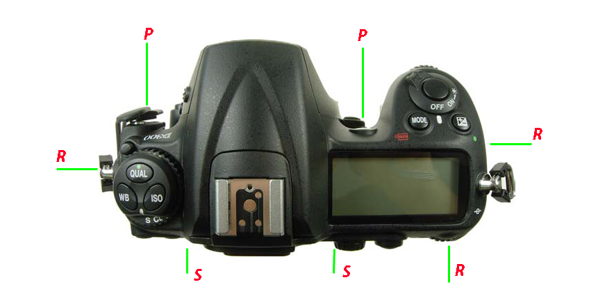
En una inspección visual tenemos que ver siete tornillos que sujetan esa tapa y que estaban ocultos bajo las gomas:
Dos iguales (marcados como P), uno bajo la lampara de ayuda al autofoco y el otro al lado del conector PC Sync.
Dos iguales (marcados como S), uno bajo el mando de la papelera y el otro bajo el mando AE-L/AF-L.
Y por último, tres iguales, que marcaremos R, y que se encuentran ubicados, uno bajo la rueda de control trasera, otro bajo el enganche de la correa (del lado de los conectores HDMI-USB...etc) y el último, en el lado opuesto, bajo el punto verde y simbolo de compensación EV.
CUIDADO AL QUITAR LA TAPA SUPERIOR: Hay un cable FPC en el lado derecho, bajo el display superior pero, por el momento, no tengo información sobre el tipo de conector que tiene en el circuito impreso. Usar la información del otro tutorial.
In a visual inspection we have to see seven screws that secure the cover and that were hidden under the gums:
Two equal (mark as P), one under the lamp helps the autofocus and the other side of the connector to PC Sync.
Two equal (mark as S), one under the command of the trash and the other under the command AE-L/AF-L.
And finally, three of a kind, we will mark R, which are located one under the rear control wheel, the other on the hook of the belt (the side of the HDMI-USB connectors ... etc) and the last, on the opposite side, under the green dot symbol EV compensation.
CARE WHEN REMOVING THE TOP COVER: There FPC cable on the right side under the upper display but, for the moment, I have no information on the type of connector you have on the board. Use the information from the other tutorial.
No hay comentarios:
Publicar un comentario
Deja aqui tu comentario o sugerencia.
Leave your comment or suggestion here.